

Utilizing CAD and Physics to Validate a Design
Written by Adrish Kar
Any engineer aiming to successfully design a certain mechanism, be it a structure as rudimentary as one of the 6 simple machines (inclined plane, lever, pulley, wedge, screw, wheel and axle) or as complex as a FRC robot, needs some method to ensure that their apparatus is fully functional. This can be done in a multitude of ways and can be located anywhere in the design process. Obviously, the most straightforward approach to this would be to simply test the mechanism during the construction/testing phase and evaluate its performance; if the mechanism works as expected, then there is no need for further steps; however, if there are any observed issues, a fall back to the brainstorm/planning phase is required to come up with possible solutions to the mechanical hindrances. Although this method is reasonably efficient for validating simpler mechanisms, an engineer might be compelled to find a potential technique for validation that is able to determine the success of a mechanism prior to the testing phase either due to the risk and complexity of testing the machine (ex. multiple subsystems of a robot) or simply in the interest of saving time and resources. There are several means to do this, including stress analysis (or stress-strain analysis), utilizing “robotics calculators” (see FRC Calculators), robot simulation, and much more! Our team has leveraged the sophisticated features of CAD (as always, the platform we’re using is Onshape) and the concepts of Newtonian physics in order to guarantee the success of our hopper/intake/outtake unit on our robot.
For our example, we will be using FRC3PO 2.0.1 (the first rendition of the second prototype of our robot). Here is the hopper (intake/outtake) and lifting unit in CAD:

FRC3PO 2.0.1
Prior to constructing and testing this subsystem, we wanted to make sure that our coupled pneumatic cylinder lifting system would offer a high enough torque to be able to lift the hopper subsystem. For this, we performed torque analysis on the systems.
First, we drew a static free body diagram of our robot with the intake/outtake system down (with the necessary predefined constants):

Static Free Body Diagram & Calculations
This might look overwhelming, but there are really only two elements we’re trying to compare: the torque generated by retraction force of the pneumatic cylinder (denoted by the quantity 𝛕2 = |L2||Fr|cos(𝛉); it is the cross product of the vectors L2 and Fr) and the torque generated by the hopper subsystem when it is lowered (denoted by the quantity 𝛕1 = |L1||m1 g| sin(𝛽); it is the cross product of the vectors L1 and m1g). For clarity, the established axis of rotation is the bottom right corner of the hopper side plate. The position of the hopper that generates the most amount of torque is when it is lowered since as the hopper is lifted, 𝛽 decreases, and since 𝛽 ∈ [0, 𝞹/2], that value of sin(𝛽) decreases as well; we assume the hopper to be at its lowest position when performing torque analysis to account for the worst-case scenario. At the very least, we’d want 𝛕1 to equal 𝛕2; of course, ideally, we want that 𝛕2 > 𝛕1.
The next step would be to utilize CAD in order to find an approximation for the weight of our hopper. Although it is a rigorous process, this can be done by either overriding the mass for or inputting the material densities for each individual element of the hopper in CAD and finally obtaining the final mass of the overall subsystem:

Determining the Mass of the Hopper through CAD
As pictured above, the mass of the hopper is hypothetically 8.044 lbs (which we will later convert to kg and multiply by g to get the force in N). It is also extremely helpful that the CAD gives us the location for the hopper’s center of mass; this (as displayed previously by the free body diagram) will be used to figure out the length of the lever arm of the hopper (L1).
The final (and probably the most challenging) step would be to use both the “mechanical blueprint” of the free body diagram (except now we’ll simply input the raw values for the constants and perform the necessary conversions along the process) and the data supplied by the CAD to obtain the net torque of the system.
We created a custom calculations spreadsheet (similar to the style of any robotics calculator) in order to do this: https://docs.google.com/spreadsheets/d/1yBtss-R-T7wEzkn8iGBbfGv-wOPDsr6vDWMzCN8G-MA/edit?usp=sharing
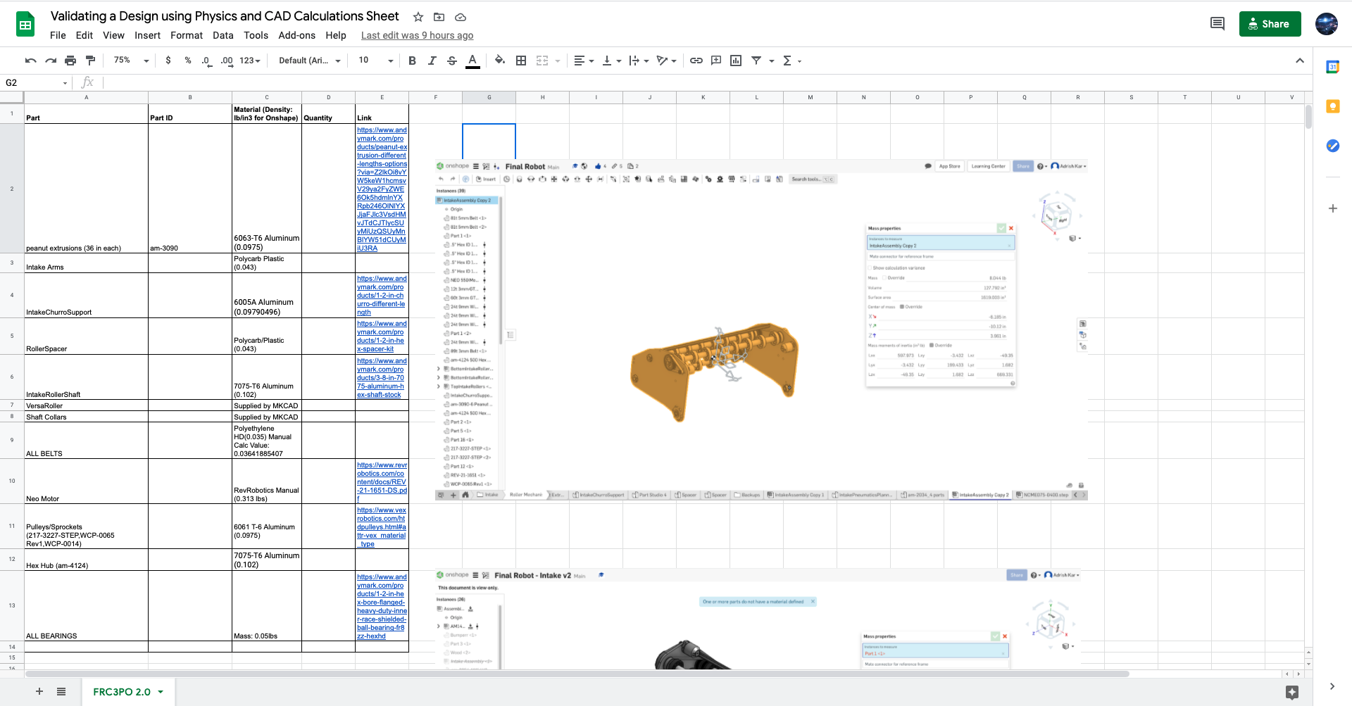
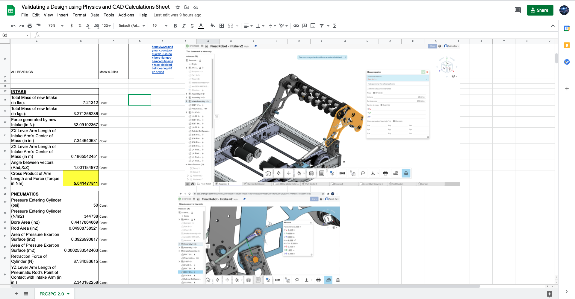
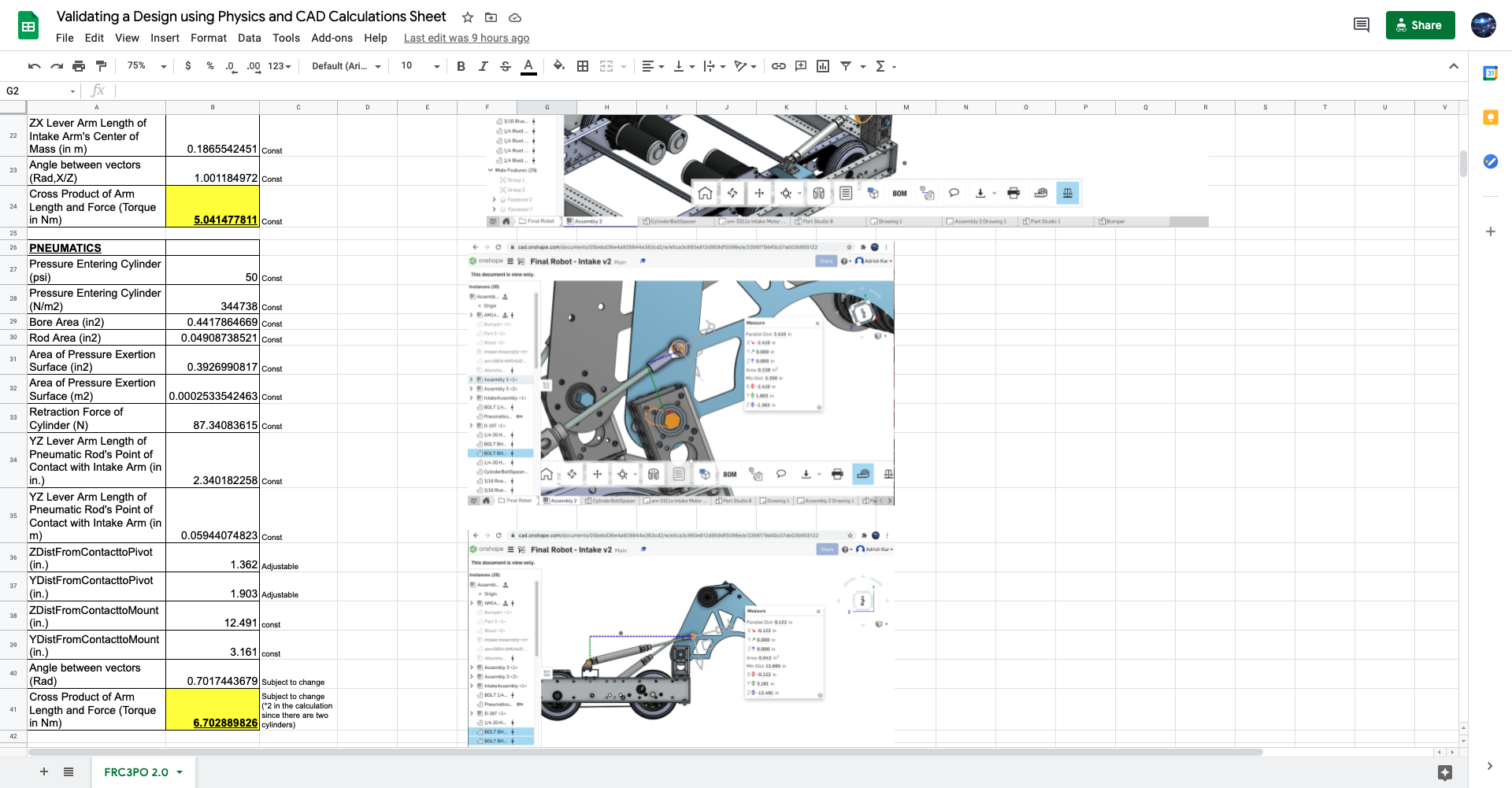
The table at the top of the spreadsheet was used to keep track of the individual material densities during the second step. You may notice that there are images to the right of the calculation tables at the left; these are images we’ve used to either record the values of certain constants according to the CAD or to reevaluate the calculations whenever we updated any aspect of our design for FRC3PO 2.0 (one example of this is the pocketing we added on the hopper side plates to reduce their mass; notice that we’ve also updated the entry of the mass of the hopper to be 7.21312 lbs rather than 8.044 lbs in the spreadsheet). As we figured out through the spreadsheet, the torque advantage for FRC3PO 2.0.1’s hopper and lifting subsystem (even with a suboptimal psi of 50 rather than 60 in our pneumatics system) is the considerable amount of ~1.66 Nm, which ensures the validity of our design!
We have also utilized this technique when validating our lifting mechanism (for which we used gears) and deciding on its gear ratio (60:24) for our final robot for the 2020-2021 build season, FRC3PO 4.0. Feel free to make a copy of the spreadsheet provided earlier and utilize it for any purpose!